Plastic and Zinc Moulds Oxford Diecast
I have had a few conversations of late about moulds, what they look like and the problems encountered when making them. Recently I was reminded that I had made a statement in a review some years ago. It went along the lines of "If you don't know what a mould looks like then you won't work at Oxford Diecast".
Technology is changing, but if you need to knock out a lot of components there is nothing better than a good traditional mould. They come in all shapes and sizes and their design is dependent on the component required and the injected material and for Oxford that means Zinc Alloy or Plastic.
You have to get to grips with these materials, as it is an understanding of these that determines how I design the products
The Zinc Alloy I refer to is the old British Standard BS1004, but is designated today as ZP5. We say Zinc but being an alloy it contains other metals predominantly aluminium (around 4%) and copper (around 1%)
Plastic Acrylonitrile Butadiene Styrene (ABS) is a common thermoplastic polymer the plastics used on many of the components – often coloured
GP a general purpose Polystyrene – used on windows
I have to decide on how we will construct our models. It is a big decision, as the final look of the product is determined at the design stage. So having done this the construction of the moulds needs to take place.
To try and better explain I will use pictures of one of our latest moulds along with my experiences to try and explain what this is all about.

This is a moulding shot it comes from the mould below, its material is ABS and will be used for two Oxford vehicles with internal codes 76M3 (BMW M3) and 76TR6 (Triumph TR6).

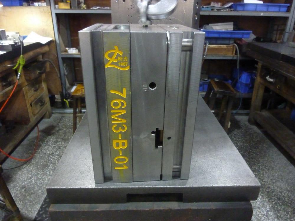
An Injection mould for plastic components. As it looks closed in our toolroom on a bench (Apr 2017) hooked up ready for lifting. Note tool coding (76M3)- Tool type code-B (Plastic -ABS) and tool number (01)). These are Oxford identifying numbers - we have thousands of moulds so identity is important.
The mould shape and size are determined at the design stage. We could have:
- Made the mould twice the size, producing two of each of the components, not one.
- Produced 10 small moulds each with one components (or more components)
- Chosen to make two moulds, one for each set of components.This mould makes ABS components for the 76M3 and 76TR6. But it is in two sections with a turntable screw.
The decision is just based on the product concerned. A balance between cost, time and money.

This mould is in manufacturing, interesting as we show the mould open, the two halves - missing the insert cavities - which have the components cavities.

In operation as the mould opens a plate brings these ejection pins forward to push the component shot of the mould. A typical cycle time being around 25 seconds for plastic, much of this taken up with the cooling time. If you eject too early the shot will be too soft (floppy). Plastic like this has a memory and once formed it wants to retain its shape. So when you find 'bowed components, the chances are they have been ejected too quickly. Also note the guide pillars, which ensure that the two haves of the mould fit together properly.

This is the other half of the mould still missing the inserts. Note the injection point of the material and also that this mould has slides.
They are required to create the inner sections of the steering wheels and the hole in the dashboard to retain the steering wheel.

So here we have the top pairing of insert which fit into the above block to make the components for the 76M3

Here is the bottom pair of inserts for the 76TR6- note we have designed the mould with a turntable sprue.
This enables us the option of running the full shot - 76M3 and 76TR6, or, just the 76M3, or just the 76TR6. This costs a little more, but avoids us running off unnecessary components.

I show here the inserts and how they mirror the shot, note the in the block which the ejection pins move through.
It was back in the 1970's when I was 16 and on the first day of my training, 7.00am in the morning, that I was introduced to my first mould. There were three lines of Injection Moulding machines, in what was known as P factory - one of the many factories at Mettoy which was spread over 14 acres in Swansea - a stone’s throw from where we are located today. There were 48 moulding machines in P factory (another 20 were in W factory a quarter of a mile away).
I was given a stopwatch, a clipboard and told to time the machines in P factory, to check the component count and produce an efficiency report, I had one hour for the machine timings and the report had to be circulated by 9.00am - not a minute earlier and not a minute later.
The first machine was an 80 ton plastic machine – an Engel, it had 64 cavities, it was full of wheels and ejecting a shot every 27 seconds. Having timed it I had to count the components, but there were only 58 coming off the mould, or was it 59, I had to recheck. Three of the cavities were locked, The other 3 were somewhere, but I couldn't find them.
Three hours later I had finished the machine timings, five hours later I had produced the report, but when I gave it to my supervisor he rejected it as the additions were wrong. I finally completed the report at 2.00pm - it had taken me seven hours. I then had to circulate it to the managers in the factory. I was new to this, I didn't know my way around, I had no help in finding out where anyone was, I just had a list of names. I didn't realise how sensitive the report was, I was like a lamb to the slaughter. I had calculated an efficiency of 74%, the manager of Plastics Factory P was not happy, he scrunched it up, threw it in the bin and talked about my parentage. Welcome to Mettoy.
I spent two months doing the same timings, but I learnt more and more. I arrived at work earlier each day to talk to the toolmakers and to understand their frustrations. I learnt about the construction of moulds, the design of the moulds,the toolmaking, the pride of the toolmakers who had made these moulds and what makes a good mould.
A few months later I spent my time in the accounts, I became familiar with the cost of a mould and how it impacted on the cost of the product and in turn the retail price of the product. It was (and still is) a constant tug of war between design, production cost and the sales price.

This is the set of components that comes off mould 76M3B01. The components are pretty clear to make out. A couple of chassis,hubs, interiors etc. The material is ABS (chosen for its properties).

This shows you the flow of the material in the mould, but there is more to it - the decision on this layout has been made for many reasons.
This mould will give me around 120 shots per hour . The mould in production has to be set in the machine. The skill in the design of the mould makes this job easier, a well balanced mould means that as the plastic flows through the channels (the runner) it helps the cavities fill in a balanced way. An out of balance mould doesn't have the correct flow patterns and can lead to flashing, or cavities not filling correctly. If the material does't reach the cavity at the right speed, it may begin to slow;it the material is the same consistency as toothpaste as it flows through the mould. The more sophisticated the mould is, the the greater the skills of the toolmaker and the machine setter. The mould shown is pretty simple. We need 'slides' to form the steering wheel holes, which is a separate part of the mould. It is called a slide as it literally slides into position as the mould closes - creating the sealed cavity.
Slides take room and there is a single slide on each of these inserts. More complex components with detail require more slides. The slides shown here move in from the outer edges of the mould itself. If a second slide were required then this would create a need for space

This image is just showing that if a second slide were required, it would need to go within the insert - taking up space and increasing the component space area.
In this tooling programme I am creating a set of moulds for for 4 products at 1:76 scale - the 76M3 and 76TR6 as shown, along with the 76VL Volvo 544 and the 76RRC Rolls Royce Corniche. A second ABS mould has also been produced for the latter two. I don' t always works with sets in this way, it depends on many variables - so I could produce 1/2/4/6/8 or even 10 products in one go. Two products means two research packages and two scans of vehicles, so a block of 10 would mean a lot of cost and research being available at the same time, My decision on the tooling configuration takes 5 seconds - plus 40 years of making decisions like this.

This is the second set of components created in a similar way for the 76VL and 76RRC
We have four sets of ABS components from these two moulds (using four inserts), but what about the other components. To compete the suite we have one window mould which contains parts for the 4 products and two diecast moulds - each producing two components.

This is mould 76M3-G-01, (Coding 76,being scale, M3 being a product code,G being Oxford plastic code for clear windows Polystyrene and 01 being sequence of 1st plastic moulds in this development).
- 1/76 BMW M3 (76M3)
- 1/76 TRIUMPH TR6 (76TR6)
- 1/76 VOLVO 544 (76VL)
- 1/76 ROLLS ROYCE CORNICHE (76RRC)
So we have far fewer components here than the ABS, so one mould covers the set.

Here is the window mould, again without the inserts fitted. There is one slide shown here - look for the channels below the pillar bars to the left and right at top of where the slides will move.

Here are the inserts ready for fitment to the mould. The slide bottom left needed for the formation of the lights for the Corniche.

Here is the ejected shot of components, (180 degrees).

On this cavity - note the ejection points (round) and to the left the plastic entry the gate. Also in this case a central guide area for optional police beacon.
That just leaves us with the diecast moulds, structurally these are different as unlike the plastic moulds shown above they need four slides. The flow of Zinc into these moulds is different to plastic, you need to get the zinc to flow into the mould as fast as possible - so the gating is not the same. The metal is over 400 degrees as it flows into these cavities, the surface starts solidifying so quickly it needs to be thumped in before it cools.

The exterior looks very similar, but beneath the surface it is very different.

We can see the mould, but again missing the inserts. We have pillars and bushes to locate the mould halves and if you look at the central section the material feed is different. This will produce two castings (top and bottom half).

BMW M3 Cavity.

The BMW M3 Cavity again. A totally different look to the plastic moulds as seen above. Four moving slides are drawn in during the injection process

The TR6 cavity

The TR6 Diecast Cavity shown again, the larger holes receive pillars that draw in the slides to create an enclosed cavity. If there is mismatch there is room for damage to the cavity or flash in production.
These diecast moulds produce a shot that looks like this

The shot as it comes of the mould. Note the different feed of metal to the cavities

How the metal is fed into the cavities, the molten zinc is spread at speed along the runners into the cavities. Too slow and the cavity is not filled, too fast and the cavity will flash. If the two cavities are not balanced then the zinc will flow though the easiest channel.

The reverse of the spreader showing injection marks.

How the zinc enters the cavity.
The speed and flow is a black art on it own, a whole new subject area, but the zinc has to enter the cavity and fill it before it cools.

The TR6 shows the overflow, a well to draw in the Zinc - all with the purpose of getting the cavity filled.

The Volvo 544 like this

The Rolls Royce Corniche like this
This just scratches the surface of mould making, there are many considerations to be made throughout the design stages - both for volume and cost reasons. Once you have come to terms with these, the rest is about the design brief and the compromise in arriving at a finalised product, because that is what it is. I aim high during the toolmaking process and then let them talk me down.
I recall in the 1970's when a good toolmaker was like an artist. A brilliant toolmaker was one who could span the spectrum of maths, was an artist and who had great communication skills. Nothing has changed.
I struggle to understand the interconnection of management and the products they make and their understanding in how they are made.
The words of one of my best toolmakers.
"The company visited us, they didn't want to see our factory, they just wanted to get a discount off the price of moulds. So we listened and then thought that they didn't care, so we increased our prices."

BMW M3

Triumph TR6

Volvo 544

Rolls Royce Corniche
Leave a comment